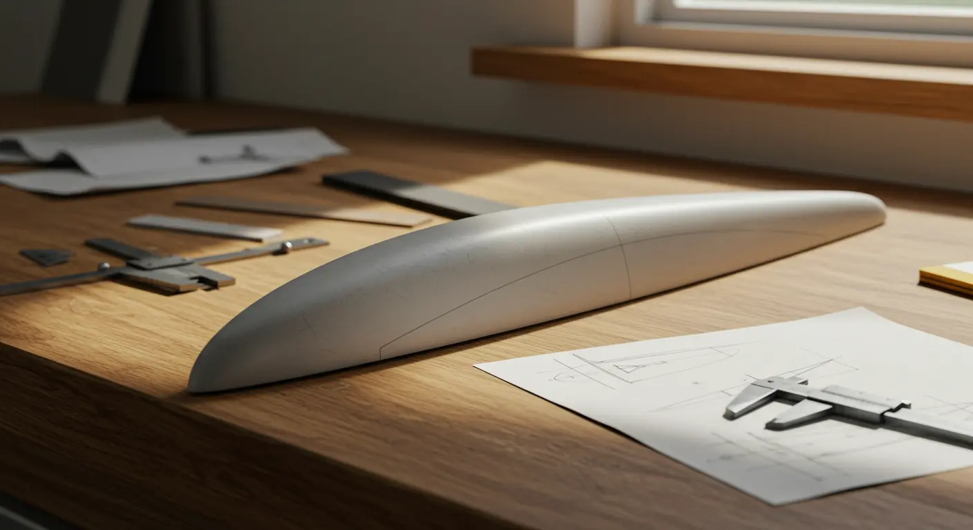
What is a Camber Line?
The camber line—also known as the mean camber line—forms the aerodynamic backbone of any airfoil, tracing an elegant curve that runs precisely midway between the upper and lower surfaces from leading edge to trailing edge.
Mathematically speaking, it represents the locus of points equidistant from both surfaces. This curve serves as the primary reference for understanding an airfoil’s curvature and intersects the chord line at both extremities.
Understanding this concept is essential because This mathematical foundation becomes crucial for engineers who need to calculate and predict airfoil performance across diverse flight conditions accurately.
Characteristics of the Camber Line
An airfoil’s aerodynamic performance is defined by several key characteristics of its camber line:
-
Shape: The line can be convex (positive camber), concave (negative camber), or flat (zero camber). Most conventional aircraft wings use positive camber to improve lift.
-
Maximum Camber: The greatest distance between the camber line and the chord line, typically expressed as a percentage of the chord length.
-
Position of Maximum Camber: The location along the chord where maximum camber occurs, also expressed as a percentage of the chord length from the leading edge.
-
Reflexed Camber: In some designs, the line curves back upward near the trailing edge. This shape helps achieve stability in tailless aircraft.
Camber Line and Lift Generation
When air encounters a cambered airfoil, something interesting happens: the upper surface presents a longer journey than the lower path.
This geometric reality forces the upper airflow to accelerate. According to Bernoulli’s principle, faster-moving air creates lower pressure—while the slower air beneath maintains higher pressure, generating that crucial upward lift force.
The camber line’s precise geometry significantly influences the coefficient of lift (CL) an airfoil can generate. A well-designed camber line enables lift generation even at zero angle of attack—something symmetrical airfoils simply cannot achieve. This characteristic is particularly valuable for aircraft during cruise conditions, as it reduces the need to maintain a nose-up attitude to generate sufficient lift, thereby minimizing drag and improving cruise efficiency.
Camber Line in Airfoil Design
Airfoil designers use the camber line as a design tool, sculpting its shape to meet exacting performance requirements. Why? Increasing the maximum lift coefficient (Climax). This increase directly translates to a lower stalling speed for aircraft using the airfoil—a crucial safety factor. An aircraft equipped with cambered wings will typically have a lower stalling speed than a similar aircraft with symmetrical airfoils, assuming comparable wing loading.
Different flight regimes demand different camber strategies. High-speed aircraft often employ subtly cambered airfoils to minimize drag, while low-speed operations benefit from more pronounced curvature that maximizes lift generation.
Practical Applications of Camber Lines
Camber is a critical design element in many practical applications:
-
Aircraft Wings: Commercial airliners use wings with optimized camber to balance lift and drag, ensuring efficiency from takeoff to cruise.
-
Rotor and Turbine Blades: Helicopter rotors and wind turbines rely on cambered blades to generate lift or extract energy from the air effectively.
-
High-Performance Vehicles: In motorsports and competitive sailing, wings, spoilers, and sails are cambered to create downforce or propulsive force with minimal drag.
-
Adaptive Airfoils: Advanced systems use “morphing” camber, employing devices like flaps or experimental continuous surfaces to alter the airfoil’s shape in-flight and optimize performance for changing conditions.
Conclusion: The Importance of Camber Lines
The camber line represents a cornerstone of aerodynamic design—its shape and characteristics directly influencing an aircraft’s lift generation, handling qualities, and overall performance envelope.
By defining airfoil curvature, the camber line allows engineers to craft wings capable of generating strong lift at reduced speeds—a capability that reduces takeoff and landing distances while expanding safety margins. This is particularly valuable in commercial aviation, where efficiency and safety are paramount.
By carefully adjusting the camber line, designers control pressure distributions around airfoils, tailoring performance for vastly different missions—whether maximizing an airliner’s range or sharpening a fighter jet’s agility.
The camber line shows how simple geometric principles can have major engineering consequences. From the Wright brothers’ pioneering gliders to today’s cutting-edge aircraft, it remains an indispensable tool in the aerodynamicist’s arsenal.

